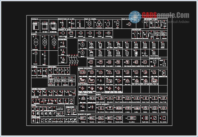
Autocad Telecom Symbols
Telecommunication is a technology in which the signals, signs, messages, writings, words, images and information of any nature can be transmitted by radio, optical, wire or other electromagnetic systems. ExamplesThere are a few samples that you see on this page which were created in the ConceptDraw DIAGRAM application by using the Electric and Telecom Plans solution. Some of the solution's capabilities as well as the professional results which you can achieve are all demonstrated here on this page.All source documents are vector graphic documents which are always available for modifying, reviewing and/or converting to many different formats, such as MS PowerPoint, PDF file, MS Visio, and many other graphic ones from the ConceptDraw Solution Park or ConceptDraw STORE. The Electric and Telecom Plans solution is available to all ConceptDraw DIAGRAM users to get installed and used while working in the ConceptDraw DIAGRAM diagramming and drawing software.
Example 1: Cafe Electrical Floor PlanThis diagram was created in ConceptDraw DIAGRAM using the combination of libraries from the Electric and Telecom Plans Solution. An experienced user spent 10 minutes creating this sample.This sample shows the detailed electrical plan on the cafe floor plan. Being an obligatory part of the building documentation, an electrical plan is created before the construction of any building or repairing the premises. This technical drawing shows the information about power, lighting, and communication at the cafe's space. Creating of electric visual plans is extremely easy process thanks to the libraries of predesigned vector elements included in Electric and Telecom Plans Solution. The use of commonly accepted lines, symbols, notations and dimensions ensures that your electrical plans will be easy-readable and correctly executed by the workers installing or repairing the electrical system and electrical equipment.
With ConceptDraw DIAGRAM you can create equally easily the electric visual plan for a single room, for an apartment, for one floor or a whole house, multi-floor building or group of buildings with showing the location of each of them and depicting the inside and outside electrical wiring. Example 2: Cinema Audio VideoThis diagram was created in ConceptDraw DIAGRAM using the combination of libraries from the Electric and Telecom Plans Solution and Sofas and Chairs Library from the Floor Plans Solution.
An experienced user spent 20 minutes creating this sample.The modern cinema is very popular due to the use of the latest digital technologies and newest audio, video and acoustic equipment to playback the high-quality video and sound. This electrical drawing sample shows the audio and video equipment used within the cinema and the scheme of their location on the cinema seating plan.
Solutions of the Building Plans Area for ConceptDraw DIAGRAM software is a real help for designers, constructors, builders, electricians, and many other people related to building and electricity. Among the mounted equipment are the speakers in walls, speakers subwoofers, video amplifiers, audio amplifiers, stereo speaker outlets, and generic automatic switchers.
All they are represented on the plan by the predesigned vector symbols from solution’s libraries and moreover have a description in a form of legend. Placed near the diagram, the legend is always before eyes explaining the symbols' sense and making your diagram understandable for everyone. Example 3: Classroom Lighting Reflected Ceiling PlanThis diagram was created in ConceptDraw DIAGRAM using the combination of libraries from the Electric and Telecom Plans Solution. An experienced user spent 10 minutes creating this sample.The qualitative lighting of the rooms and other spaces, especially the classrooms in schools, the auditoriums in universities, colleges and other educational institutions, the premises in kindergartens is an incredibly important thing affecting both the health of children and the effectiveness of their training. That's why the architectural lighting engineering and design is a special field, the specialists of which are occupied by the professional buildings' illumination and possess knowledge in lighting norms and lighting design, as well as in lighting nature, technologies in this field, physics of production and distribution of the light. This sample illustrates the lighting reflected ceiling plan for the classroom that must be well illuminated room. All lighting objects, among which the enclosed ceiling luminaires, 1 and 2 pole switches, and binding switches with the luminaire, were taken from the libraries of the ConceptDraw's Electric and Telecom Plans solution.
Their list with semantic descriptions is also represented in the diagram. Example 4: Electrical PlanThis diagram was created in ConceptDraw DIAGRAM using the combination of libraries from the Electric and Telecom Plans Solution and Floor Plans Solution. An experienced user spent 15 minutes creating this sample.This sample illustrates the apartment electrical plan. Actually, it is a plan of layout the sockets, double sockets, and switched sockets, and a plan of wiring between them. The place of installing the main control device is also marked.
Don’t afraid to use the colors when designing your residential electric plan, electrical and telecom wireless plan in ConceptDraw DIAGRAM application — the colors make your plans more attractive, understandable and successful. The wiring is depicted with red color and immediately catches in eyes. It is a strict electrical plan, without distracting stakeholders' attention to the apartment design, the furniture and other accessories typically located within any apartment, but such electrical items as lamps, lighting fixtures, and electrical appliances can be easily added to it in any moment to make the plan maximally extensive and detailed. The beforehand thought-out apartment electrical and telecom plan allows creating comfortable conditions for living in it. Example 5: SwitchesThis diagram was created in ConceptDraw DIAGRAM using the combination of libraries from the Electric and Telecom Plans Solution and Floor Plans Solution. An experienced user spent 15 minutes creating this sample.This electrical plan sample is a bright example of the switches layout plan.

The lighting switches are the devices of operation the lights, electrical outlets, electrical equipment and electrical appliances. You can easily move switches on the plan to arrange them in an ideal way, this will give the ability to avoid errors at the further mounting electrical equipment in a building. Different kinds of switches were invented and are mounted today, and powerful ConceptDraw DIAGRAM vector graphics software gives you the possibility and flexibility of choice — all variety of them is available at the Switches library of Electric and Telecom Plans solution.
Autocad Symbols Telecom
The large hall represented in this diagram is equipped with several 8-light bars located symmetrically on both sides of the room, close to the walls and at the same distance from each other. The tools of ConceptDraw DIAGRAM allow keeping the same distance between the lamps and other light fixtures on the plan without efforts. What I Need to Get StartedBoth ConceptDraw DIAGRAM diagramming and drawing software and the Electric and Telecom Plans solution can help creating the floor plans you need. The Electric and Telecom Plans solution can be found in the Building Plans area of ConceptDraw STORE application that can be downloaded from this site. Make sure that both ConceptDraw DIAGRAM and ConceptDraw STORE applications are installed on your computer before you get started.


Autocad Drawing Symbols
How to installAfter ConceptDraw STORE and ConceptDraw DIAGRAM are downloaded and installed, you can install the Electric and Telecom Plans solution from the ConceptDraw STORE.Start usingTo make sure that you are doing it all right, use the pre-designed symbols from the stencil libraries from the solution to make your drawings look smart and professional. Also, the pre-made examples from this solution can be used as drafts so your own drawings can be based on them. Using the samples, you can always change their structures, colors and data.